MAGNETIC WAVE
USER GUIDE

Product Overview
Concept of operation
The figure above shows that Magnetic Wave consists of a transmitter and a receiver placed on opposite sides of a metal wall such as bulkhead or deck. The transmitter, which is aligned and fixed in a location representing the spot to be located on the opposite side, emits energy pulses (dashed red arrow) that pass through the metal plate and are sensed by the receiver on the other side of the plate. This energy, which is detectable on the opposite side of the metal plate, falls off in strength away from center of the transmit antenna.
The receiver displays the amplitude of the received energy pulses so that an operator moving the receiver up-down and right-left in the plane of the metal plate can observe how received signal strength increases and decreases in different positions.
When the operator using the receiver detects the point on the metal plate where signal strength is maximum, the detected point of maximum signal strength represents the location of the transmitter on the opposite side of the plate.
Once the point of highest signal strength is determined, the system can be used to communicate between the transmitter and the receiver. In the figure below, the transmitter has GO and STOP buttons that allow an operator with the transmitter to communicate GO and STOP messages, via coded pulses in the transmitted energy stream.
Locating the transmitter using the receiver
The figure below shows how to locate the transmitter position on the opposite side of a metal barrier. This figure shows the antenna attached to the receiver but the antenna, when plugged into the receiver via its cord, can be moved all by itself, as long as it is electrically connected to the receiver.
In the figure, an operator began by placing the center of the receive antenna at Point ‘A’ on the left, then moving the receiver and attached antenna to the right to Point ‘C’, passing through Point ‘B.” In the figure, the antenna and receiver are shown together, but the antenna –connected through a cable plugged in to the receiver’s antenna jack–is typically scanned separately across a bulkhead or deck with the receiver placed on a stable surface nearby.
As the receiver moved, the received transmitter signal on the receiver display screen increased in amplitude up to Point ‘B’, then decreased as the receiver/antenna moved to Point ‘C.’
The location at which the signal peaks, represents the location on the opposite side of the metal barrier where the transmitter has been placed.
Understanding the three components of the system
MagneticWave has three components.
The function of the transmitter is to generate signals that pass through a metal barrier for the purpose of beaconing position to a receiver on the opposite side of a barrier. A detachable antenna, connected to the transmitter, radiates the transmitted signals through the barrier, where they are picked up by a detachable antenna on the receiver unit on the opposite side of a barrier and displayed on the screen of a receiver.
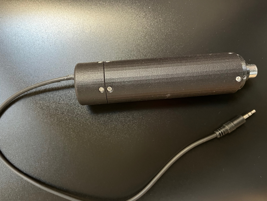
The transmitter
The top view shows the control panel and antenna assembly. The knob in the center controls the output power level that is radiated from the antenna, power increases as the knob is turned clockwise.
Shown below are four labeled indicator lights. The top indicator, a green power light shows that the unit is powered on. The light below turns red when the battery is failing to charge properly, and the indicator light third from the top lights up red if the antenna or antenna connection is faulty. The bottom-most indicator turns on red when the battery charge is getting too low.
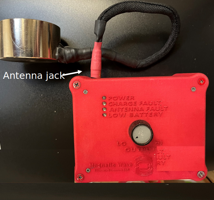
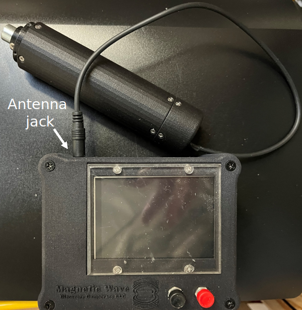
The antenna plugs into the antenna jack, which is visible in the front view, below.

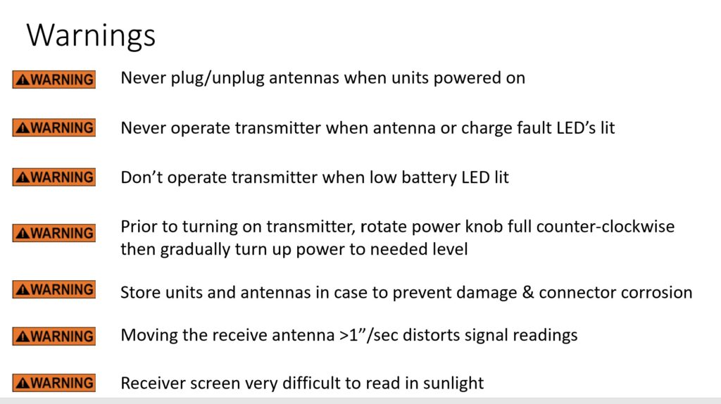
WARNING: Never connect or disconnect the antenna while the transmitter is powered on. Doing so may damage the transmitter and void the warranty.
On the right side of the transmitter is a special battery charging plug that attaches to a dedicated battery charger supplied with the unit (described in more detail later).

The left side of the transmitter has an ON/OFF slide switch and a factory maintenance port, normally not used by operators.

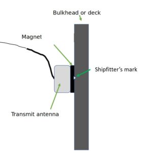
The transmit antenna can be held against a bulkhead, deck or overhead manually, or, more conveniently, can be attached using the magnet mounted on the face of the transmit antenna, as shown below. Typically, the transmit antenna is centered on a shipfitter’s mark showing where hot work is to be performed
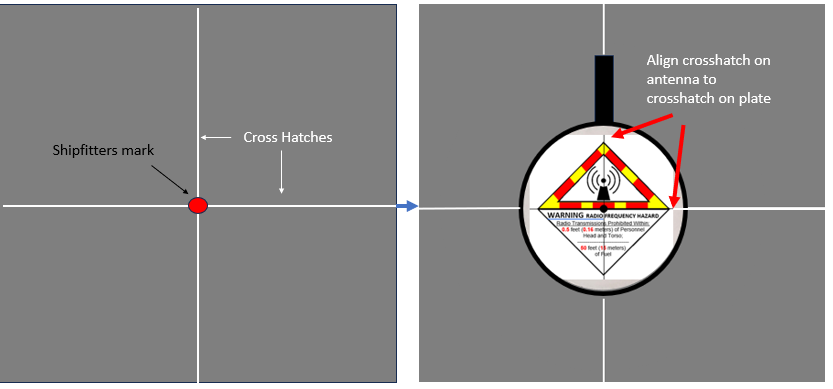
The transmit antenna has a lable on the back with a crosshatch pattern for precise alignment with a shipfitter’s mark, as shown below. Apply a crosshatch through the shipfitter’s mark, as shown on the left below, then, as shown on the right, align the crosshatch pattern on the back of the tranmsit antenna to the crosshatch on the bulkhead or deck plate. The black circle in the middle of the antenna’s crosshatch pattern aligns with the shipfitter’s mark when the two crosshatch patterns are aligned
Safety Warning
THE TRANSMITTWER ANTENNA, AT PEAK POWER, EMITS AN AC MAGNETIC FIELD OVER 160 GAUSS AT THE FACE OF THE ANTENNA, AND, WITH OR WITHOUT POWER, THE PERMANENT MAGNET HAS A DC MAGNETIC FIELD OVER 990 GAUSS ON THE FRONT FACE OF THE ANTENNA. THEREFORE, THE TRANSMIT ANTENNA MUST AT ALL TIMES BE KEPT AT LEAST 1 FOOT AWAY FROM ANY PACEMAKER OR ICD. THE SYSTEM SHALL NEVER BE OPERATED BY OR NEAR ANY INDIVIDUAL WITH A PACEMAKER OR ICD. IN ADDITION, EVEN USERS WITHOUT PACEMAKERS MUST NEVER TOUCH THE TRANSMIT ANTENNA WITH ANY PART OF THE BODY WHEN THE TRANSMITTER IS TURNED ON.
Charging the transmitter battery
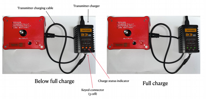
The transmitter battery is charged with the charger and charge cable, shown below.
To charge the transmitter, plug the round end of the transmitter charge cable into the right side of the transmitter, and the other end of the cable, which is keyed to only insert in one orientation, into the “3 Cell” input jack on the charger unit. When the transmitter battery is low, red indicator LED’s will illuminate, as shown on the left. After the the transmitter battery has been fully charged, the three red LED’s will turn green.
The transmitter charger comes with a power cord that plugs directly into a 110 VAC outlet.
Do not leave the battery charger plugged into the transmitter unattended, and always remove the charger immediately after charge is complete, as indicated by the change from red to green lights.
Using premium transmitter battery charger
Charging the transmitter battery
MagneticWave also offers a premium transmitter battery charger that supports shorter charging times and is fully UL listed. Operation of the premium charger is described below
Components of the premium charging system.
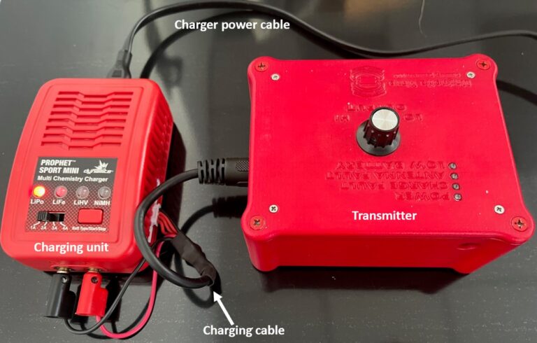
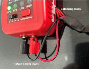
The system, shown above, consists of a charging unit, shown on the left, a power cord for the charging unit which is a 120 VAC, two connector lead, and a custom charging cable connecting the charger to the 7 pin DIN transmitter recharge port, as shown.
Connecting the charger
Proper connection of the charger to the transmitter is essential both for safety and good function. Always disconnect the charger power cord before connecting the charging leads.
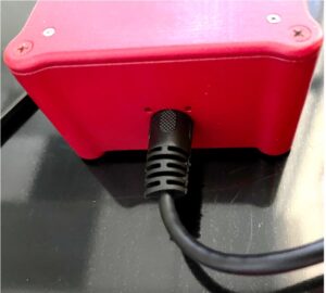
At the transmitter charge port, firmly plug in the 7 pin DIN connector, making sure the connector is all the way in and fits snuggly and shown below.
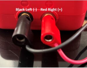
Next. Plug the red and black banana plug leads into the high current jacks, taking great care to insure that the black lead goes into the left, “-“ jack while the red lead goers into the right “+” jack.
Incorrect connection can damage the equipment and create unacceptable heat and smoke.
Finally, as shown below, plug in the keyed, 4 wire balancing lead into the “3S” jack on the charger’s side.
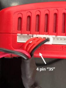
When completed, the charger-side charging cable connection should appear as below
Charging procedure
Make sure all connections are snug and secure. Failure to accomplish this may prevent proper charging.
Once all connections are made, plug the charger power cord in.
DO NOT Attempt to change the factory settings, making sure that the charging level slide switch in the far left position, and that only the LiPo light on the far left lights up. Changing the slide switch position from 1A to another setting could damage the transmitter and void the warranty.
If, by pressing the Red Batt Type/start/stop button on the right in the wrong manner, battery type is changed, do not attempt to charge. Call or email MagneticWave ( 01-844-777-3946, eric@magnetic-wave.com) for instructions on resetting battery type.t
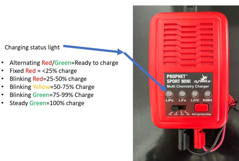
When you first connect the charger power cord, you will see the LiPo light flashing alternating red and green, indicating that the unit is ready to charge. To charge the transmitter, press and hold the red button on the right for 3 seconds.
You will then see different colors in the LiPo LED, depending upon charge statrus.
The chart above, describes the meaning of different color patterns.
Once the steady Green LED appears, charging is complete.
DO NOT leave the charger connected to the transmitter after charging is complete and NEVER charge the transmitter unattended or overnight.
The receiver
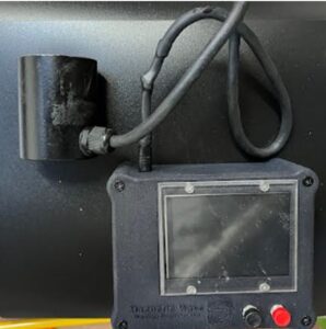
The top of receiver with an antenna attached, above, shows the normal user view of the receiver.
The main feature is a screen that displays the signal propagated through the metal barrier to the antenna. The white number on the left of the display shows the instantaneous signal strength, while the green number below it shows a value averaged over the previous 3 seconds. When momentary signal variations are large, due to movement artifacts or transient electrical noise, it is sometimes useful to use the more stable green value over the white value to locate the transmitter.
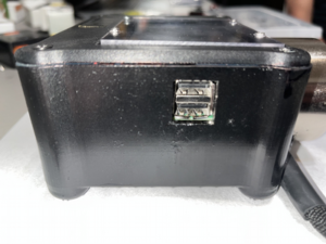
The right side of the receiver has two USB ports for future expansion capability and factory diagnostics (currently disabled and not used by operators).
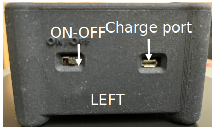
The left side of the receiver has a micro USB recharging port (right of photo) and an ON/OFF switch
The receive antenna is connected at the phono jack port, shown on the right of the photo below.
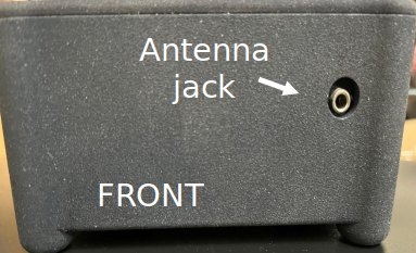
Warning. Never connect the antenna while the receiver is powered up. Doing so could damage the receiver and will void the warranty
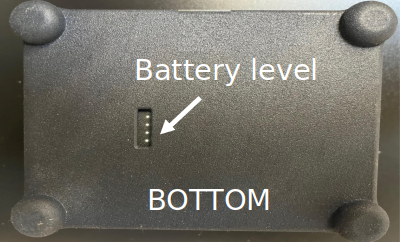
The base of the receiver has a port with 4 LED’s indicating the level of battery charge, where each LED represents 25% of the charge (4 lit LED’s connote a 100% charge).
Using the receiver
After the receiver’s battery is fully charged, turn it on using the slide switch on the left side of the enclosure. A screen will appear showing the waveforms of the received energy.
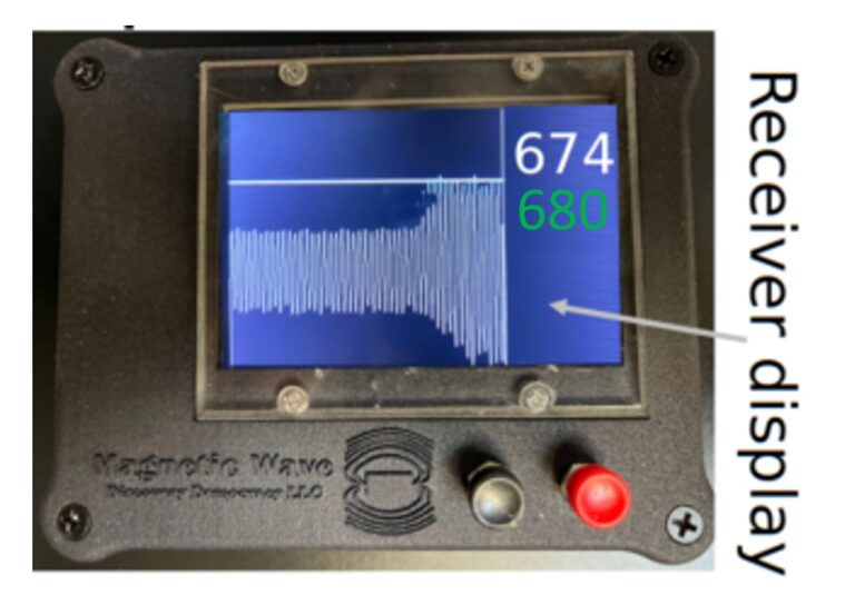
Below are the different components of the receiver screen display
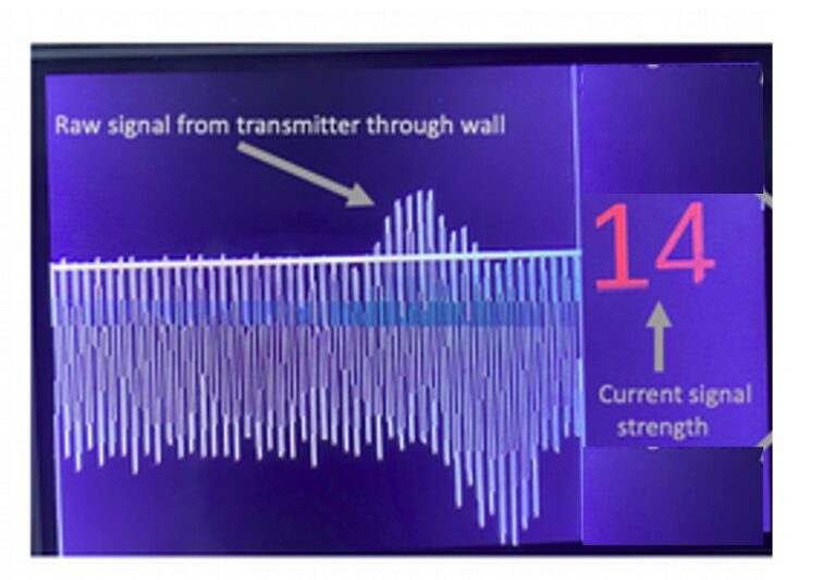
The signal picked up by the receive antenna is displayed as a moving trace that scrolls from right-to-left as new energy from the transmitter is received. The amplitude of the signal just received (i.e. on the far right) is shown numerically in red and also indicated by a horizontal bar that slides up and down with signal amplitude. In this example, the signal strength, and level of the horizontal bar, is ’14’.
The screen displays 6 seconds of signal trace history, allowing operators to compare current readings (on the far right) with readings in the previous 6 seconds of operation. In this example, the operator had moved the receiver/antenna assembly slowly across the transmitter’s location on the opposite side of a bulkhead, encountering a peak signal strength in the middle of the trace, or about 3 seconds prior to the instant this photo was taken. Notice that the peak signal rises above the “current strength” horizontal bar indicator, revealing that a stronger signal than that of the current (far right) signal had been received.
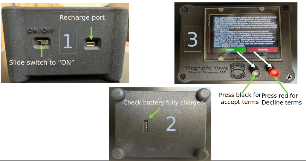
The receiver is turned on and made ready for use with 3 steps shown below.
Antennas
There are two types of receive antennas, whose use depends on the thickness of metal plate involved as well as obstructions such as conduit, junction boxes, insulation, plumbing, structural members and other objects commonly attached to metal walls.
The standard antenna, which is supplied with each transmitter and receiver, is suitable for applications where the metal wall is no more than 1/2” thick, with insulation no more than 2” thick, and where there are no obstructions that would interfere with the placement of the antenna near the wall’s surface.
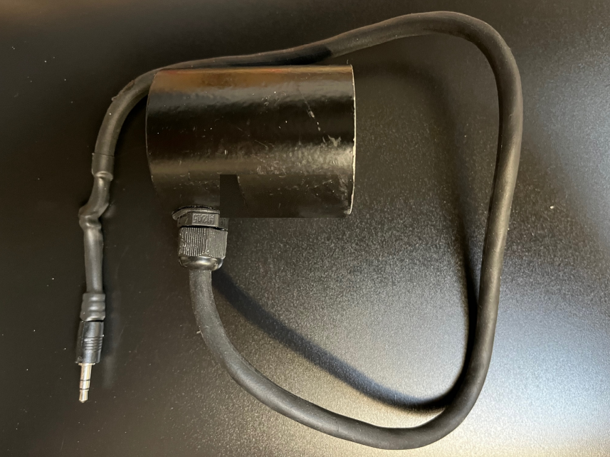
Standard antenna
Transmit antenna
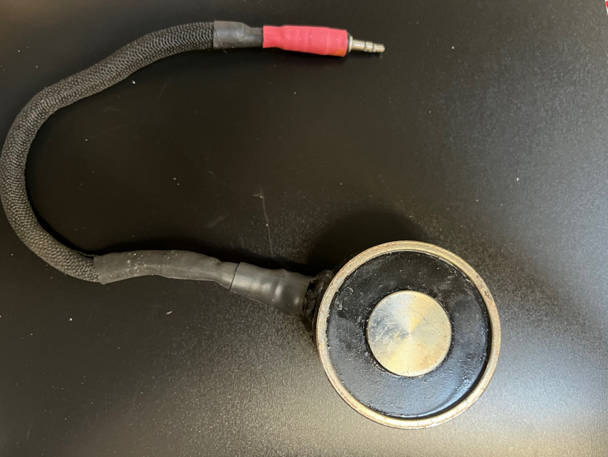
Ultra-sensitive long probe Receive antenna
Receiver with long probe antenna
When wall thicknesses exceeds 1/2”, and with some grades of steel, a more sensitive receive antenna is required to establish an acceptable signal. The ultra-sensitive antenna will work, except in rare cases, with steel plate up to 3” thick plus two inches of insulation. The ultra-sensitive antennas connect via a 3.5mm phono connector, like the other antennas. Another advantage of the ultrasensitive antenna is that it can pick up a transmitter signal farther away than a standard antenna, and thus can help locate the transmitter faster due to less time “hunting” for a signal.
Marking the location of the transmit antenna
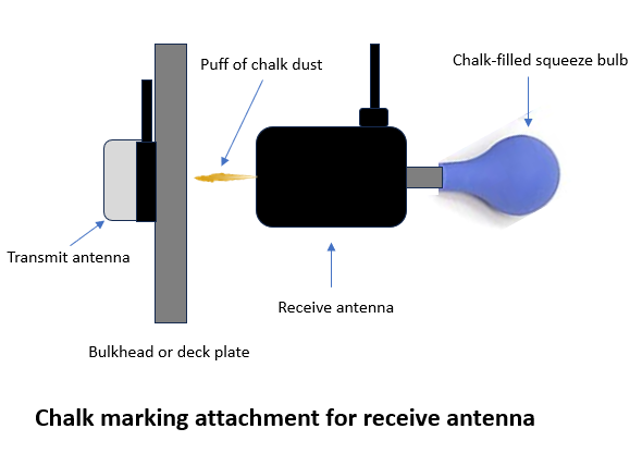
In order to mark the location that the receive antenna identififies, a chalk marker attachment is provided with each unit. The blue, chalk filled bulb, provided with each system, attaches to a hollow nipple screwed into the back of each receive antenna. When a user believes they have located the transmit antenna position, the user squeezes the bulb, propelling chalk dust through the nipple and a hole in the receive antenna. The chalk dust adheres to the metal plate or lagging, denoting the estimated position of the tranmsit antenna on the adjacent side. This feature enables one-handed operation and marking, which is useful for cramped locations or spots hard to reach with both hands. The bulb can be refilled using a funnel or syringe with any commerically available chalk. To use the chalk marker the first time, remove the black seal and cork that prevent chalk leakage during shipping.
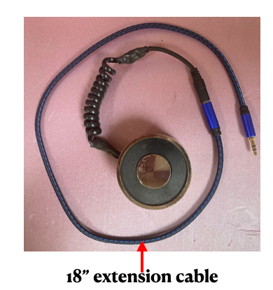
Extension cable
Each antenna comes with an 18”, standard 3.5mm stereo extension cable (below), with female and male connectors, to allow operators to separate the antenna from transmitter/receiver units, place the units where they will not move, then to move the separated antenna by hand, Operating the antenna separate from the main chassis can be useful in tight spaces, or in hard-to-reach places, such the the underside of metal plate floors.
The extension cable will slightly reduce the sensitivity of the antenna in receiver mode, and slightly decrease the power of signals from the transmitter, but should be useable in most applications. Multiple extension cables can be hooked together to achieve 36″ or 48″ total length, as needed.
NOTE: BE SURE TO INSERT ANTENNA PLUGS FIRMLY AND COMPLETLEY INTO EXTENSION CABLE JACK , OR ANTENNAS WON’T WORK AND THE TRANMSITTER MAY BE DAMAGED BY POOR CONNECTION
Precisely locating a transmitter position through a metal wall
In most cases, except where very thick or unusual alloys in the wall are involved, when then is extreme electromagnetic interference or when there are many obstructions mounted on a wall where it is desired to pinpoint a specific position, precisely locating a transmitter’s position (specifically, the center of the transmitter antenna on the opposite side of the barrier) is straightforward using a multi-step process.
The steps for location finding
1) Using standard techniques, (measuring off of drawings, and known common fiducial points such as conduit throughways) determine the most likely point on one wall corresponding to a desired point on the opposite side of the wall. In all that follows, we will refer to the side of the wall with a known point “the known side” and the side of the opposite wall, where it is desired to find an exact corresponding point, the “unknown” side. WARNING: SUCH STANDARD TECHNIQUES MUST BE THE PRIMARY MEANS OF LOCATING POSITION. MAGNETIC WAVE MUST ONLY AUGMENT, NEVER REPLACE DIRECT MEASUREMENT METHODS
2) When the most likely position on the “unknown side” has been marked, one operator will place a transmitter antenna center on the correct point on the “known side,” then turn on the transmitter, selecting a power level appropriate for the thickness of metal, type of metal and amount of intervening insulation or other obstacles. The transmitter may be fixed in place with a permanent magnet, or held in place with a tripod mounted to the floor of the transmitter.
3) After the transmitter has been turned on, (and this act has been communicated via banging on the wall, or some other means) the operator on the “unknown side” will turn on the receiver, and place the center of the receive antenna over the marked spot.
4) Then, the “unknown side operator “ with the receiver will make sure that they have acquired a transmitter signal.
The figure on the left below is what the receiver screen looks like when there is only “noise”, and no real signal. The random spikes are simply magnified random noise. They appear large because of the auto-scale feature of the system, where the displayed range is automatically adjusted according to the level of signal strength. Autoscaling makes sure that the full range of a signal can be seen, without “clipping off” of very low or very high signals. Thus, the vertical size of a signal on the display, all by itself, does not convey absolute signal strength. Rather the vertical extent of a signal, with reference to the the white number on the right is what conveys absolute signal strength.
The figure on the far left below, represents the case where the initial estimate of the correct position on the “unknown side” is so far in error that there is no discernible signal at all. The middle figure shows how the signal appears in a weak form, when first acquired. This middle scan represents what an operator would see when moving from a “noise only” region into a “weak signal region” signifying that the receiver has moved closer to the true transmitter location.
On the far right a scan is shown in which the user progressively moved closer to to true position of the transmitter. In this example, the operator made two discrete moves, starting in a weak signal area and moving to progressively stronger regions.
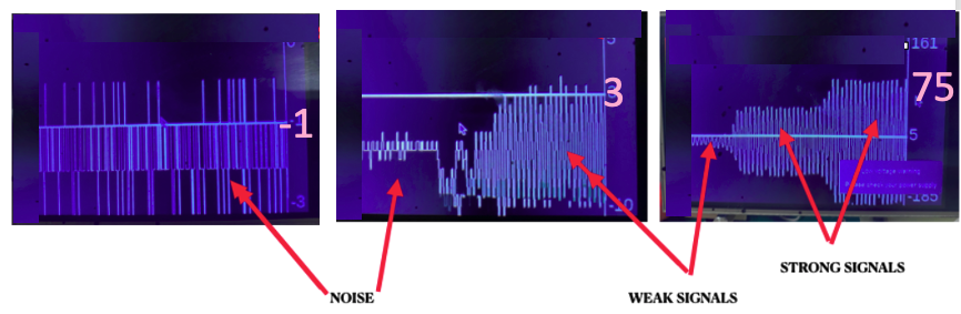
Noise (far left), weak signal (right side of middle) and song signals (far right)
In the middle figure, the difference between “noise” and weak signal can be clearly seen in two respects. First, the signal is larger and second, the signal is much more regular and less random.
5) Once a weak signal has been acquired, the operator should make a horizontal scan to find the point of greatest signal strength along that horizontal path. This point is determined by passing the receiver slowly across the point of estimated strongest signal strength and the signal level number on the right, noting the point at which movement in either left or right direction decreases signal amplitude on the scan.
Motion should be no greater than 1”/sec, in order to avoid motion artifacts that mask the desired signal (more about this later). Also, the vertical and horizontal scans should be made in straight, perpendicular lines to the greatest extent possible, because slight deviations away from the straight path of motion of the receive antenna can sometimes provide misleading increases or decreases in signal strength.
6) At the point of greatest signal strength along the horizontal path, the operator should then move the receiver vertically, again until the strongest signal strength is achieved. As before, once the operator believes the strongest signal has been found they should slowly move the receiver onto and off of this point, ensuring that numeric values, shown on the far right, decrease away from the indicated point.
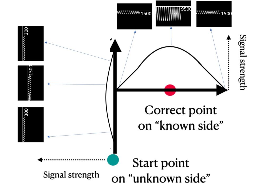
7) Operators should mark the point of greatest signal strength, then repeat the process several times to insure accurate location estimation. The figure below depicts the left/right up down scan pattern just described, where the operator started to the left and down of the correct point, started with and up/down scan, then, upon locating the peak signal strength inn up/down pattern, moved left and right until finding the peak on a horizontal pattern. The signal that would display on the receiver at difference points is depicted to the left of the vertical scan and above the horizontal scan.
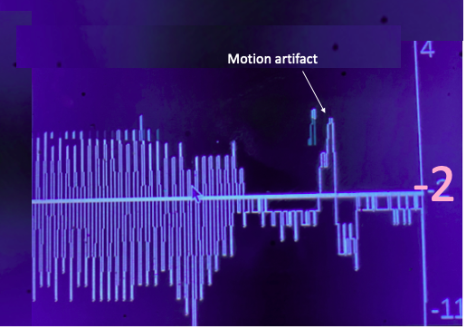
8) The importance of controlling speed of sensor motion across wall surface. When the receiver antenna moves across a ferrous metal plate, that movement, all by itself, will generate a slow, but potentially strong signal that can, if the motion is fast enough and signal weak enough, swamp out the signal and make location detection difficult, The figure below presents an example of a motion artifact, where the artifact occurred after the receiver antenna moved quickly away from an area where the signal was present to where no signal was present, creating an artifact.
In this example, with a very weak or absent signal, the motion artifact is not easily confused with a legitimate signal. However, too rapid of scan motion of the receiver when there is a signal present, can create confusion about whether a strong signal is or is not present.
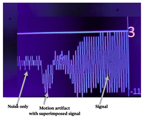
Motion artifact with superimposed real signal
In this second example, an operator moves the receiver antenna quickly from a position with no real signal (noise only) to one with a weak signal. Because of the motion artifact, the amplitude (negative excursion) of the signal appears to be larger than it really is, as is evident from the gradual increase in signal strength as the receiver moves closer to the transmitter position.
Thus, when the antenna is placed directly on a metal plate, the antenna must be moved at a low enough velocity, typically around 1″/second, to avoid motion artifacts. The receive antenna can be moved at higher velocities without significant artifact, as the distance between the antenna and the bare metal wall increases. For this reason, locating the tranmsitter can actually occur faster and easier when there is lagging over the plate steel through which location-finding is performed, even though the absolute signal strength is reduced relative to direct antenna-on-plate contact.
In many cases, the fastest way to locate the transmitter is to start by scanning the receive antenna a few inches away from the bulkhead or deck as you might a “magic wand” and to look for the general region where the signal is strongest. Because the receive antenna can be moved at a faster rate without motion artifacts when displaced a few inches from a metal plate, this technique can quickly identify the general region of the transmitter while minimizing motion artifact due to close proximity to metal plate. Once the general region of the transmitter has been identified, more delibertate careful movement of the receive antenna made against the bulkhead or deck can precisely pinpoint the transmit antenna location..
Finally, operators should bear in mind that the horizontal/vertical scan method just described can give misleading increases or decreases in signal strength when the receive antenna is scanned over insulation or some other covering whose thickness or separation from the underlying metal plate is not uniform across the full path of receive antenna motion (air pockets, warping or other distortions move the receive antenna away from the transmitter in a direction perpendicular to the bulkhead or overhead plate, reducing signal strength, even when the receive antenna is getting closer to the vertical or horizontal position of the transmitter). If such thickness anomalies are suspected, or other difficulty finding the strongest signal is experienced ,users should try getting close to the transmitter position by lifting the receive antenna and placing it down on the metal or covering in different places to start to zero in on the transmitter position.
Plate thickness and insulation
As just mentioned, the radial distance (along an axis perpendicular, or into and out of the bulkhead or overhead plate) between the transmit and receive antennas influences both signal strength and the accuracy of location. As plate thickness increases, or insulation or other material is placed between the transmit and receive antennas, signal strength decreases, and the rate at which the signal decreases away from the point of perfect alignment between transmit and receive antennas, also decreases, as shown in the figure below.
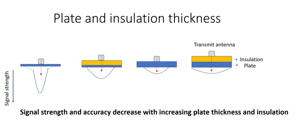
Even when different steel plates have the same thickness, the strength of the received signal may not be the same across all plates, even with identical alloy designations, because variations in steel properties attenuate magnetic signals differently. Such attenuation differences can even occur at different locations on the same plate.
However, for aluminum, brick, sheetrock and other non-ferrous materials, there should be very little variation from one location to the other at constant wall thickness.
Safety warnings
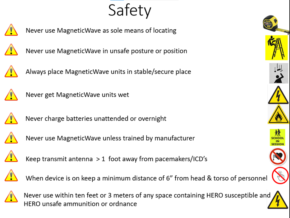
- Never use the Magnetic Wave system as the sole or primary means of locating positions or communication. The Magnetic Wave system is not guaranteed to either locate or communicate reliably under arbitrary conditions of metal wall thickness, metal barrier alloy make-up, presence of electromagnetic and optical interference, operator behavior to presence of obstacles and insulation.
- Do not charge batteries of receivers, transceivers, transmitters or remotes unattended or overnight
- When using devices near flying debris, especially hot debris such as slag, cover the units with transparent shield material similar to that that used on faceplate of welder’s helmets
- Do not use the dedicated transmitter or the transmitter in a transceiver within three feet of any person wearing a pacemaker
- Keep Magnetic Wave units dry at all times
- Use and store Magnetic Wave systems in environments ranging from 0-35 degrees Celsius.
- Keep operating Magnetic Wave transmit antennas at least three feet away from devices (such as magnetic stripe or magnetic disc drives) at all times.
- Do not under any circumstances attempt to open the chassis case of transmitters, transceivers, receivers or remotes. Doing so could pose a shock hazard candor damage sensitive equipment.
- Do not, under any circumstances, attempt to communicate directly with Magnetic wave embedded processors, for example, using the USB A maintenance/update ports.
- Do not operate the Magnetic Wave system without completing Magnetic Wave Certified in-person or on-line training available at www.magneticwave.com/training. Operating the system without training will lead to unreliable locating and communicating.
- Only operate the units in accordance with Magnetic Wave certified training and Operator’s manual. Use of the Magnetic Wave system outside the required procedures, described in training materials and the Operators Manual, will lead to unreliable communication and locating.
- Never stand on an unstable support or place the transmitter or receiver units where they can fall or be displaced.
- Never try to place antennas in hard-to-access locations in such a way the operator must strain or position themselves in an unsafe or uncomfortable position
- The Receiver display screen is designed for indoor use only. The receiver screen can only be used in sunlight when great care is taken to shield the screen from sunlight
- When device is on, keep a minimum distance of 6 inches from head and torso of personnel
- Never use device within 10 feet or 3 meters of any space that contains HERO susceptible & HERO unsafe ammunition or ordnance
Troubleshooting guide
- Transmitter or Receiver won’t turn on
Check battery charge. IF charge not the problem, return to factory
- Received signal not detectable in receiver
Insure transmit/receive antennas firmly in female connectors of units and extension cables
- Noise interferes with signal
Move antenna/receiver away from noise source, or increase transmit power
- Transmit antenna fault light shows red
Return unit to factory
- Transmit charge fault lights red or transmitter won’t charge
Make sure charging cable plugs pushed in snuggly. If that fails, return unit to factory
- Receive antenna movement artifact obscures signal
Increase transmitter power
System specification
SCOPE
The specifications (below) for system performance (e.g. location accuracy, allowed plate thickness) depend upon which combinations of components are used.
The highest level of accuracy and plate thickness is achieved using a transmitter set on the highest output power setting with a receiver on the opposite side of a barrier equipped with an ultra-sensitive antenna, whereas lesser performance (accuracy and plate thickness) is achieved with other combinations of antennas and transmit output power.
Thus, specifications here are tied to specific combinations of components.
One last point: all specifications are described for typical alloys of steel plates, types of insulation and environmental conditions such as ambient electromagnetic noise (both radio frequency and optical). Performance numbers described here will not be achieved with arbitrary alloys, mill scale present on metal plates, types of insulation and electromagnetic interference. Although the reference manual describes ways to work around interference, Magnetic Wave makes no guarantee of system performance for all types and thicknesses of materials and working environments. Also, all specifications assume that operators are fully trained on using the system and use it according to instructions in training material and the operator’s manual.
Location accuracy
The accuracy of location-finding of the center of the transmit antenna located on one side, measured on the opposite side of a barrier depends primarily upon four factors
1) Plate thickness
2) Insulation thickness
3) Type of receive antenna
4) Training and skill of the operator
Other factors, such as strong electromagnetic interference and mechanical vibration of the plate due to operation of nearby machinery can degrade location accuracy as well, but these have not yet been fully characterized and have not proven to be problematic under conditions tested thus far. This specification will be updated as more data on these other factors becomes available.
Accuracy degrades with increasing plate thickness, presence of insulation, and sometimes, use of the long probe antenna.
The tables below, which show accuracies for different plate thicknesses and antenna types present cases where no insulation is present and where 2” of insulation is present. N/A indicates use of a particular antenna for a particular thickness is not recommended.
Table 1
| .25” | .375” | .5” | 1” | 2” |
Standard | .5” | .5” | .5” | N/A | N/A |
| |||||
Ultra-sensitive | N/A | N/A | .5” | .75” | .75” |
Location accuracy with different antennas and plate thicknesses: No insulation
Table 2
| .25” | .375” | .5” | 1” | 2” |
Standard | 1” | 1” | 1.5” | N/A | N/A |
| |||||
Ultra-sensitive | N/A | N/A | 1’ | 1” | 1” |
Location accuracy with different antennas and plate thicknesses: 2” insulation
For example, with plate .375” thick or less, an ultra-sensitive antenna is not required, whereas with plate of greater thickness than .5”, only an ultrasensitive antenna will yield acceptable results.
The data in the tables above demonstrates that, when very high accuracy is desired, insulation should be removed to allow the receive antenna to abut directly on a bare metal surface.
Thus, an appropriate area of insulation to be removed (for example a 3” X 3” patch) can be identified and marked based upon a first pass of the receiver with insulation in place, then, after the insulation patch is removed, a second pass of the receiver antenna on bare metal under the recently removed insulation can locate the desired point at greater accuracy, as indicated by the tables.
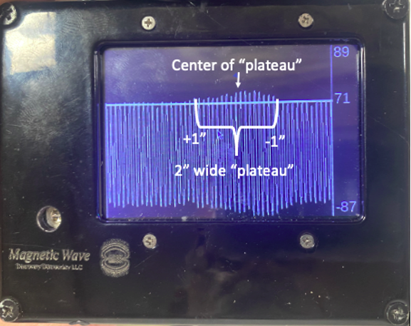
With practice, operators can improve their ability to pinpoint correct locations by learning a few tricks, such as “splitting the difference” on a “signal plateau”
The figure below, which is a reconstruction of signal strength vs position relative to the true location of a transmit antenna, as measured by an ultrasensitive antenna on the opposite side of the plate from the transmitter, shows such a “signal plateau” for a 2” plate with 2” insulation.
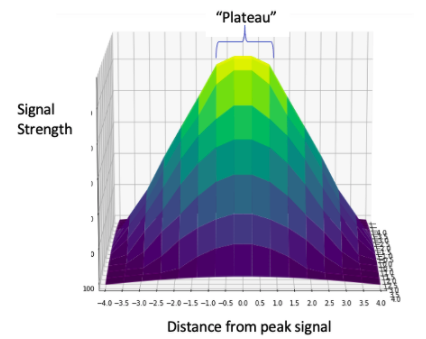
The figure shows that, as the receiver antenna is moved away from the point of peak signal strengths (yellow), signal strength falls gradually within an inch of the peak, then falls rapidly at distances greater than 1”
Thus, there is a roughly 2” plateau (+/- 1” from the peak signal position), where movement of the receiver antenna will produce relatively small changes in signal strength, making precise locating more difficult.
However, skilled operators can identify the “edges” of this plateau, then identify the peak position as midway between those two edges, because signal strength falls off uniformly in all directions away from a signal peak.
The figure below is a screen shot after an operator slowly moved the receiver antenna about 2” across the peak signal location. The shallow hump in the signal amplitude represents slight, but persistent changes in signal amplitude, corresponding to the “plateau” region of the previous figure. By taking careful note of the receiver antenna position when the midpoint of the hump occurs, an operator can identify the correct spot to within +/- .5” even though the “plateau” itself may span as much as 2”, as shown below.
Communication between transmitter & receiver through plate/insulation
Plate thickness Up to 3” steel plate
Characteristics with standard antennas
Battery life
Receiver 3 hours (continuous)
Transmitter 3 hours (continuous): low power
1.5 hours (continuous): high power
Battery recharge
Receiver 5V Micro USB, 1- hour recharge
Transmitter 11.1V, DIN, 1-hour recharge
Size (Both transmitter and receiver chassis) 4.75” W X 3.75” H X 2.25” D
Size (Standard antenna) 2.25” diameter X 1.375” depth
Weight
Chassis 1.4 lbs.
Antenna 1.1 lbs.
Chassis + antenna 2.5 lbs.
Characteristics with long probe receive antenna
Weight
Chassis 1.4 lbs.
Antenna 1.3 lbs.
Chassis + antenna (narrow probe) 2.7 lbs.
Characteristics of ultra-sensitive antenna (using extension cord to chassis)
Size 1” diameter X 7” long
Weight 1.5 lbs.