MAGNETIC WAVE
USER GUIDE

Product Overview
Concept of operation
The figure below shows that Magnetic Wave consists of a transmitter and a receiver placed on opposite sides of a metal wall such as bulkhead or deck. The transmitter, which is aligned and fixed in a location representing the spot to be located on the opposite side, emits energy pulses (dashed red arrow) that pass through the metal plate and are sensed by the receiver on the other side of the plate. This energy, which is detectable on the opposite side of the metal plate, falls off in strength away from center of the transmit antenna.
The receiver displays the amplitude of the received energy pulses so that an operator moving the receiver up-down and right-left in the plane of the metal plate can observe how received signal strength increases and decreases in different positions.
When the operator using the receiver detects the point on the metal plate where signal strength is maximum, the detected point of maximum signal strength represents the location of the transmitter on the opposite side of the plate.
Magnetic Wave System Overview
The round antennas depicted in this figure, positioned at the metal barrier, are standard antennas that ship with every system. However, as metal plate thickness and intervening insulation (e.g. hull-board) increase, a more sensitive and powerful antenna is required, as described later.
Locating the transmitter using the receiver
The figure below shows how to locate the transmitter position on the opposite side of a metal barrier.
In the figure, an operator began by placing the center of the receive antenna at Point ‘A’ on the left, then moving the receiver and attached antenna to the right to Point ‘C’, passing through Point ‘B.” for convenience, the antenna and receiver are shown together, but typically the receiver will be placed in a stable location and the antenna will be moved across the bulkhead or deck separately, connected to the receiver through a cable that plugs into the receiver’s antenna jack.
As the receiver moved, the received transmitter signal on the receiver display screen increased in amplitude up to Point ‘B’, then decreased as the receiver/antenna moved to Point ‘C.’
The location at which the signal peaks, represents the location on the opposite side of the metal barrier where the transmitter has been placed.
The figure below is a close up the the receiver screen, showing the signal strengths at points A, B and C respectively.
Understanding the three components of the system
Magnetic wave has four components.
The function of the transmitter is to generate signals that pass through a metal barrier for the purpose of communicating position and GO/STOP messages to a receiver on the opposite side of a barrier. A detachable antenna, connected to the transmitter, radiates the transmitted signals through the barrier, where they are picked up by a detachable antenna on the receiver unit on the opposite side of a barrier and displayed on the screen of a receiver. When a transmitter operator presses a GO or STOP button on the transmitter, a coded signal passes from the transmitter to the receiver, then, from the receiver to a small remote device held, or worn in a welders helmet or hard that emits colored lights and tones signifying GO or STOP.
The transmitter
The figures below show different three views of the transmitter

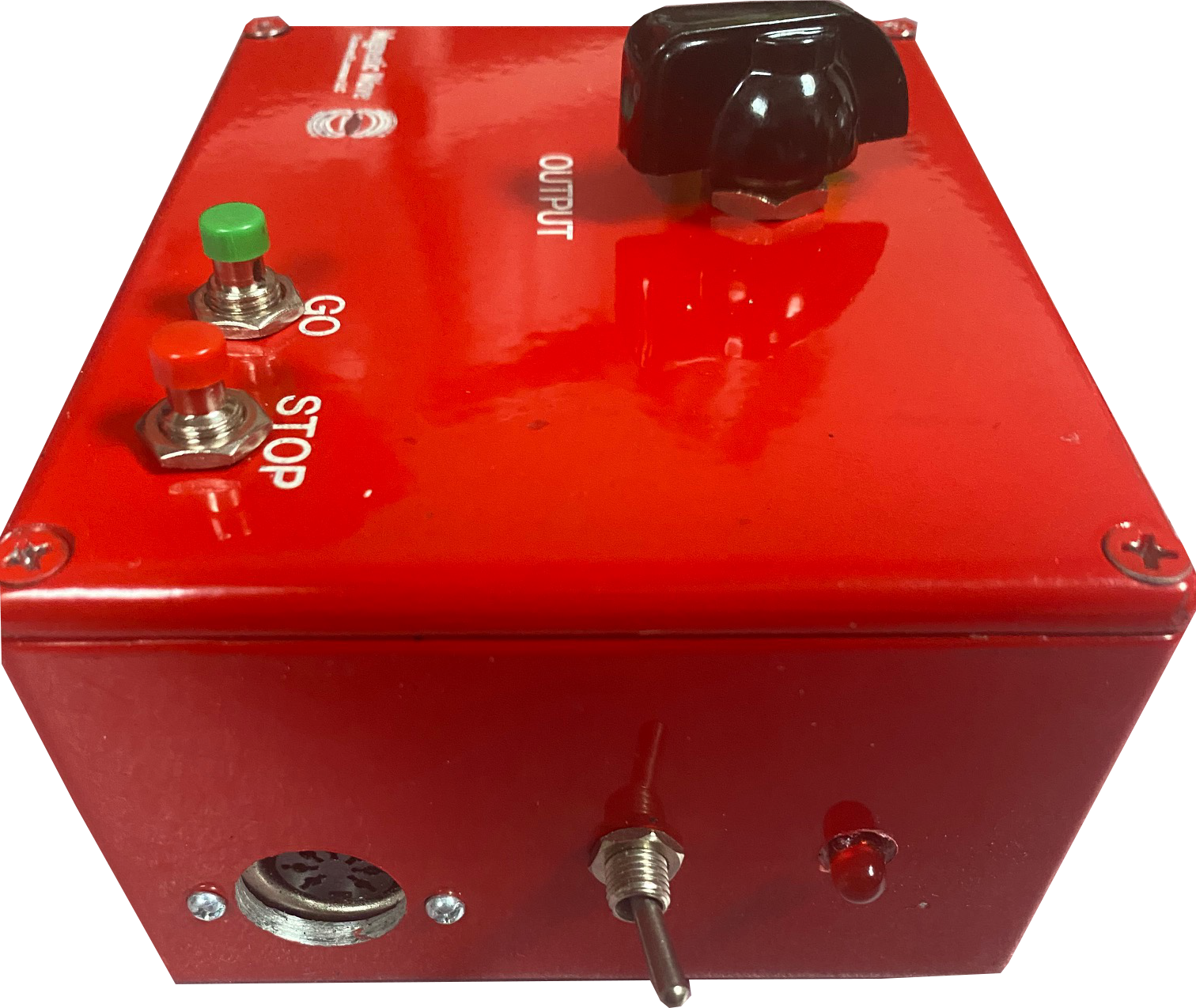
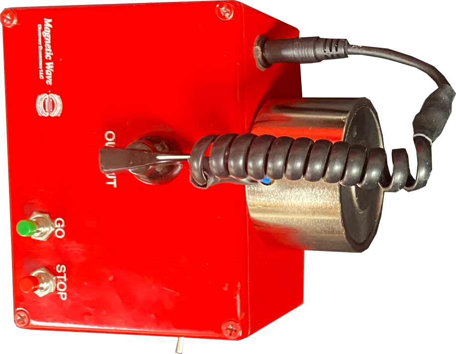
Top view of Transmitter
The top view shows the control panel and antenna assembly. The knob in the center controls the output power level that is radiated from the antenna, power increases as the knob is turned clockwise.
The green and red buttons respectively signal GO and STOP to the receiver.
The detachable antenna screws on to the front of the unit, with a signal cable, shown on the front-left, plugging into the antenna jack, which are visible in the front view, below
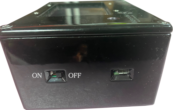
Front view of transmitter
The transmitter is turned on and off with a toggle switch on the side, next to a ON/OFF indicator LED.
To the left of the power switch, a battery charging port accepts a connector from an external charger (not shown)
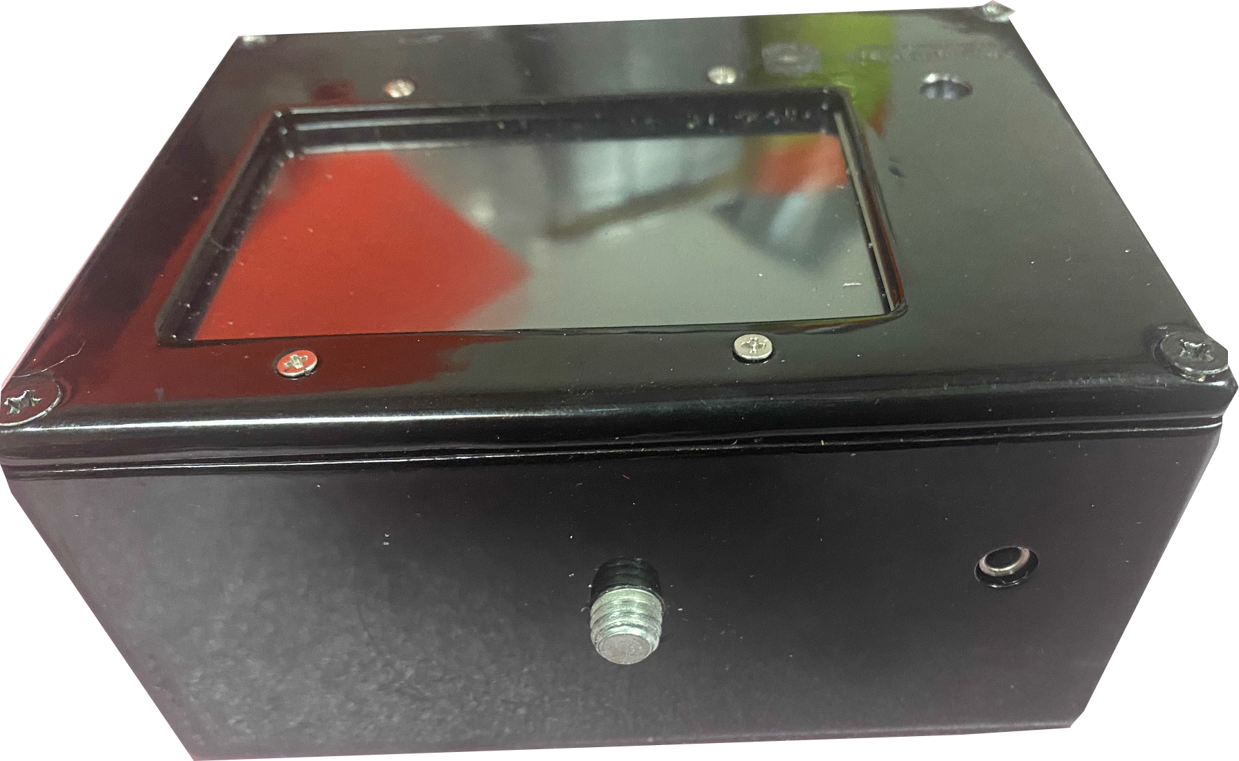
Side view of transmitter
The underside of the transmitter, below, has a threaded 1/4 20 hole to accept a tripod mount.
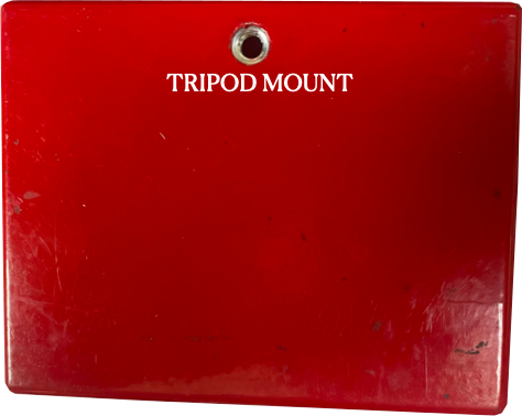
Transmitter base
Charging the transmitter battery
The transmitter operates at higher power than the receiver, and thus uses a different battery and charger.
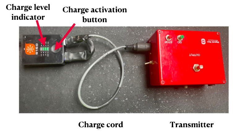
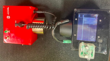
A separate charging unit and special cable, shown below are provided for the transmitter. To charge the transmitter battery, connect the cable as shown, then press twice on the charge unit button.
The number of bars on the charge unit shows the charge remaining in the transmitter battery. While charging, the bar corresponding to the next level of charging to be attained blinks. In this photo, the transmitter battery is 3/4 charged, so the fourth bar would be blinking.
Charging the transmitter battery
When charging is complete, the fourth bar will glow steadily, and the charging unit will sound a “fully charged” beep.
Never charge the transmitter with the transmit power switch in the ON position.
Also, never operate the unit when its charge is plugged in.
The receiver
The top of receiver with an antenna attached is shown below.
The main feature is a screen that displays the signal propagated through the metal barrier to the antenna.
On the left of the screen is a small opening that the receiver uses to transmit GO/STOP messages to the remote device.
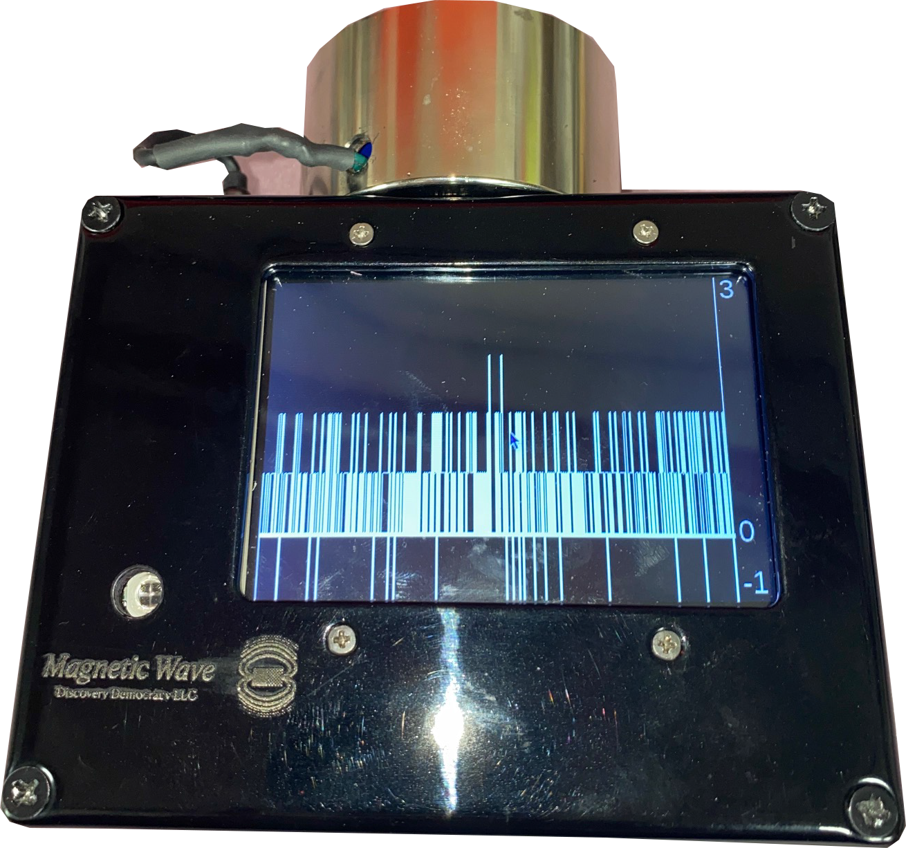
Top view of receiver
Left side of receiver
Right side of receiver
Receiver fron
The receiver’s left side is shown below, with an ON/OFF switch and a micro USB port for recharging the battery. The battery can be recharged from any 5 Volt USB charging unit, including the one supplied with the receive.
The receiver’s left side is shown below, with an ON/OFF switch and a micro USB port for recharging the battery. The battery can be recharged from any 5 Volt USB charging unit, including the one supplied with the receive.
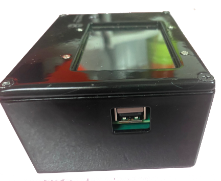
The front of the receiver, below has a 5/16 18 stud that screws into the back of a detachable antenna, as well as an antenna cable jack, shown on the right.
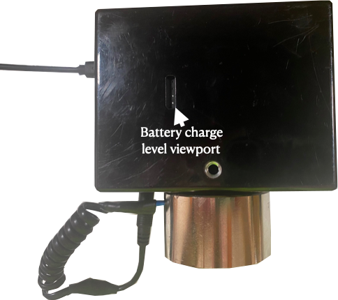
The bottom of the receiver, below, has a threaded 1/4” 20 hole for mounting to a tripod, and a viewing port for a battery level indicator. In this photo, three out of four white LED’s are lit, indicating that the battery has 3/4 charge remaining.
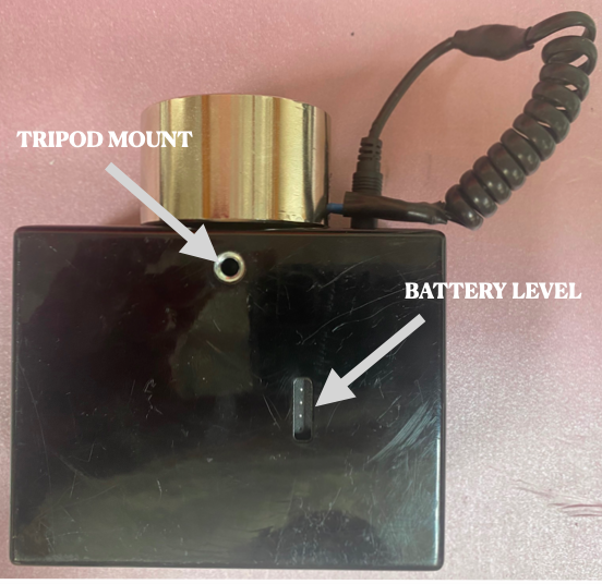
Underside of receiver/transceiver
The transceiver
Magnetic Wave also offers a combined Transmitter/Receiver (called TRANSCEIVER) , which can simplify inventory, logistics support and provide two way communication between operators on opposite sides of a metal wall, when desired.
The transceiver, shown below, is identical to a receiver, except that three controls have been added:
1) A transmit/receive toggle switch to put the unit in either transmit or receive mode
2) A GO Button, for sending a GO message when the device is in transmitter mode
3) A STOP Button for sending the a STOP message, when the device in in transmit mode.
The charging, attaching of antennas and other features of the transceiver are identical to that of the
receiver, including ON/OFF charging ports, battery charge viewing port and special USB A Data port.
Transceiver unit top view
The power source in the transceiver is less powerful than that of a dedicated transmitter, so that the transceiver cannot operate through steel plate greater than 1/2” thick in transmit mode, unless the ultra-sensitive antenna is used for the receiver on the opposite side of the wall.
Changing the receiver/transceiver battery
The underside of receiver/transceiver units have a viewport for determining the remaining charge on the system (independent of the low battery message on the displays screen).
In the figure below, two out four white LED lights are lit, indicating the the unit’s battery is half charged.
When a Micro USB cable, connected to a standard 5 V USB source is plugged into the micro USB port on the left side of the device, the LEDs will light, with the LED representing the next charging level blinking.
When all four white LEDs remain on constantly, the unit is fully charged.
Never charge batteries while the units are turned on, and never operate the devices with the battery charger attached.
Bottom view of Receiver/Transceiver
Using the receiver/transceiver
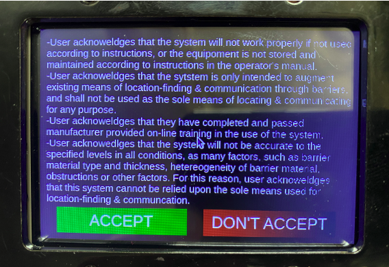
After the receiver’s battery is fully charged, turn it on using the slide switch on the left side of the enclosure.iA launch screen will appear after system boot-up, stipulating the terms and conditions of use. To continue using the system, operators must hot the green “ACCEPT” icon on the touchscreen (using a fingernail or stylus).
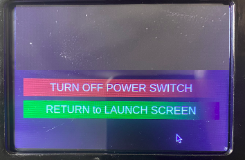
If the terms of use are not accepted, press the “DON”T ACCEPT” icon on the touchscreen, which will bring up a screen specifying that the unit should be turned off, using the slide switch, or should be returned to the launch screen, in case the operator elects to accept the conditions of use.
Below are the different components of the receiver screen display that appear after operators press the “ACCEPT” icon on the touchscreen..
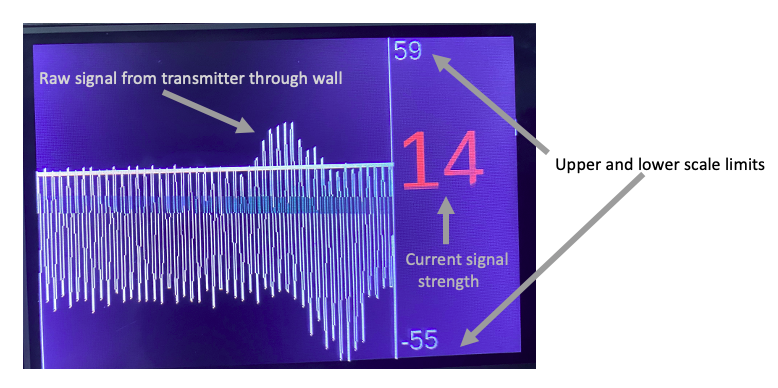
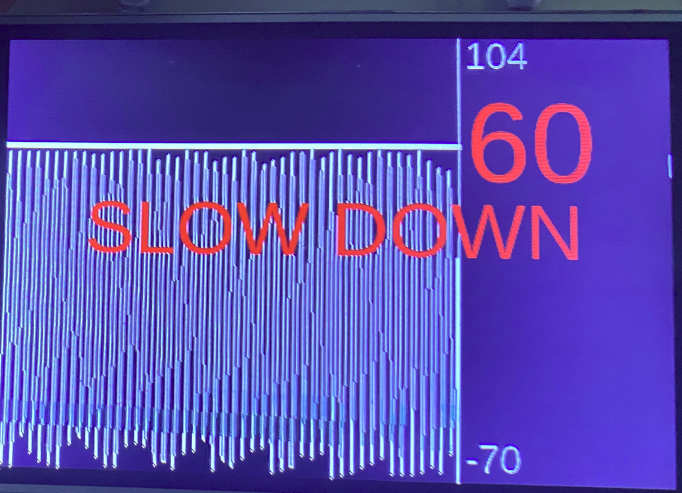
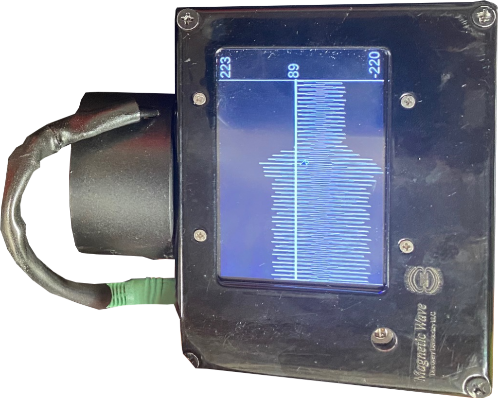
The signal picked up by the receive antenna is displayed as a moving trace that scrolls from right-to-left as new energy from the transmitter is received. The amplitude of the signal just received (i.e. on the far right) is shown numerically in red and also indicated by a horizontal bar that slides up and down with signal amplitude. In this example, the signal strength, and level of the horizontal bar, is ’14’.
The screen displays 6 seconds of signal trace history, allowing operators to compare current readings (on the far right) with readings in the previous 6 seconds of operation. In this example, the operator had moved the receiver/antenna assembly slowly across the transmitter’s location on the opposite side of a bulkhead, encountering a peak signal strength in the middle of the trace, or about 3 seconds prior to the instant this photo was taken. Notice that the peak signal rises above the “current strength” horizontal bar indicator, revealing that a stronger signal than that of the current (far right) signal had been received.
When the operator moves the unit too fast, creating undesired signal artifacts, a “SLOWDOWN” message will appear, as shown below, cueing the operator to decrease the scanning speed.
GO/STOP/URGENT communication
During some kinds of operation across metal walls, at least two operators will participate in the work.
Inasmuch as metal walls and barriers can be hard to communicate through, due to blocking of radio commutation, or blocking of sound, it is desirable for one of the operators to quickly communicate with another operator on the opposite side of the wall.
For example, a safety watcher on one side of a barrier might be watching for instances when construction activity on the opposite side of the barrier, such as cutting, impinges upon, or is about to impinge upon sensitive areas such as plumbing or electrical conduit. In those instances, the safety watch may use the
Magnetic Wave system to communicate with the construction operator in order to prevent damage. In this scenario, the safety watch would have a transmitter and the construction operator a receiver, such that, when the safety watch presses the STOP button, a STOP message would be relayed to the construction operator on the opposite side of the wall. To send “URGENT” simultaneously press both the GO and STOP buttons.
Similarly, when it were safe for an operator to proceed, the safety watch would press the GO button, causing the GO message to be relayed to the operator. In extreme situations, such as fires, one operator may want to signal URGENT in order to communicate that instant action is needed.
The receiver units transmit GO/STOP/URGENT signals to remote units, that may be mounted in helmets, such that a GO causes one kind of tone and a steady green light in the remote to come on briefly, a STOP causes a steady RED light and different tone, while an URGENT causes the remote a loud buzz and flashing red light.
In some cases, it will be feasible for the operator to directly see this message on the receiver screen, as shown below.
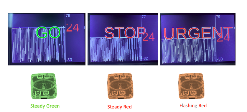
GO /STOP/URGENT messages on receiver
However, it is often the case that operators performing construction work may not be able to shift their attention from their immediate work to a receiver display screen. For such cases, a remote signaling device, shown below, flashes GREEN when a GO signal is received and plays a loud “GO” tone, but flashes RED and plays a more urgent “STOP” tone when a STOP signal is received.
Each receiver has an optical transmitter that radiates GO and STOP codes, that are in turn picked up by optical receivers in the remote units, signaling to the remote to display and play the appropriate color light flash and audio tone. These remote units may be worn by operators or mounted inside or outside a helmet on the operator.
The remote units are described in detail later in the “Remote unit” section.
Antennas
There are three types of antennas, whose use depends on the thickness of metal plate involved as well as obstructions such as conduit, junction boxes, insulation, plumbing, structural members and other objects commonly attached to metal walls.
The standard antenna, which is supplied with each transmitter and receiver, is suitable for applications where the metal wall is less than 1/2” thick, with insulation no more than 2” thick, and where the are no obstructions that would interfere with the placement of the antenna near the wall’s surface.
Standard antenna
A threaded 5/16 18 hole attaches the antenna to the transmitter or receiver corresponding threaded stud, and a 3.5mm stereo male connector plugs into the phono jack, also on the front of receivers and transmitters, as depicted below.
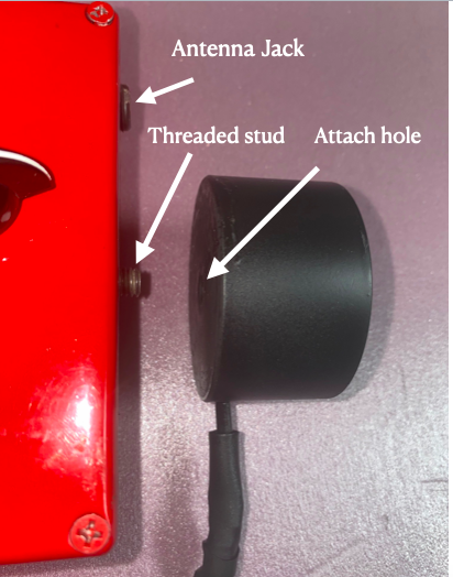
Attachment of antenna to units
In cases where obstructions get in the way of either the transmit or receive antenna, an antenna, shown, below, with a narrow probe extension, 1/2” in diameter and 6” long is useful. These antennas mount the same way as the standard antenna, to a threaded stud and connect using the same 3.5mm phono type connector.
This antenna can be used with wall thicknesses up to 1/2”, again with no more than 2” of insulation so that only the antenna is scanned across the metal barrier surface, with the receiver unit itself.
Antenna with extension probe
Probe extension/marker for tight or remote spaces
For applications where a bulkhead or deck surface is cluttered with fixtures, impeding access, or is in a hard-to-reach location, an antenna extender handle can be helpful, when used with an extension cord that allows the receiver or transmitter chassis to be separated from the antenna. In hard-to-reach and remote locations, often only one hand can be used due to space restrictions, so the handle extension comes with a colored chalk marking system suitable for one-handed operation. As shown below, when a bulb in the handle is pressed, colored chalk is expelled from a small tube at the probe’s end, allowing one-handed marking of the desired location.
When wall thicknesses exceeds 1/2”, and with some grades of steel, a more sensitive receive antenna is required to establish an acceptable signal. The ultra-sensitive antenna below will work, except in rare cases, with steel plate up to 3” thick plus two inches of insulation. These ultra-sensitive antennas connect via a 3.5mm phono connector, like the other antennas, but are too large and heavy to attach to the units themselves.
Instead, ultra-sensitive antennas are best used with an extension cable, and a handgrip or small tripod, with the receiver unit themselves, nearby and stationary The tripod shown with the above ultra-sensitive antenna, provided with each ultra-sensitive antenna, collapses into a pistol grip so that operators can hold the antenna under its center of gravity.
Ultrasensitive antenna
Extension cable
Each antenna comes with an 18”, standard 3.5mm stereo extension cable (below), with female and male connectors, to allow operators to separate the antenna from transmitter/receiver units, place the units where they will not move, then to move the separated antenna by hand, Operating the antenna separate from the main chassis can be useful in tight spaces, or in hard-to-reach places, such the the underside of metal plate floors.
The extension cable will slightly reduce the sensitivity of the antenna in receiver mode, and slightly decrease the power of signals from the transmitter, but should be useable in most applications. Multiple extension cables can be hooked together to achieve 36″ or 48″ total length, as needed.
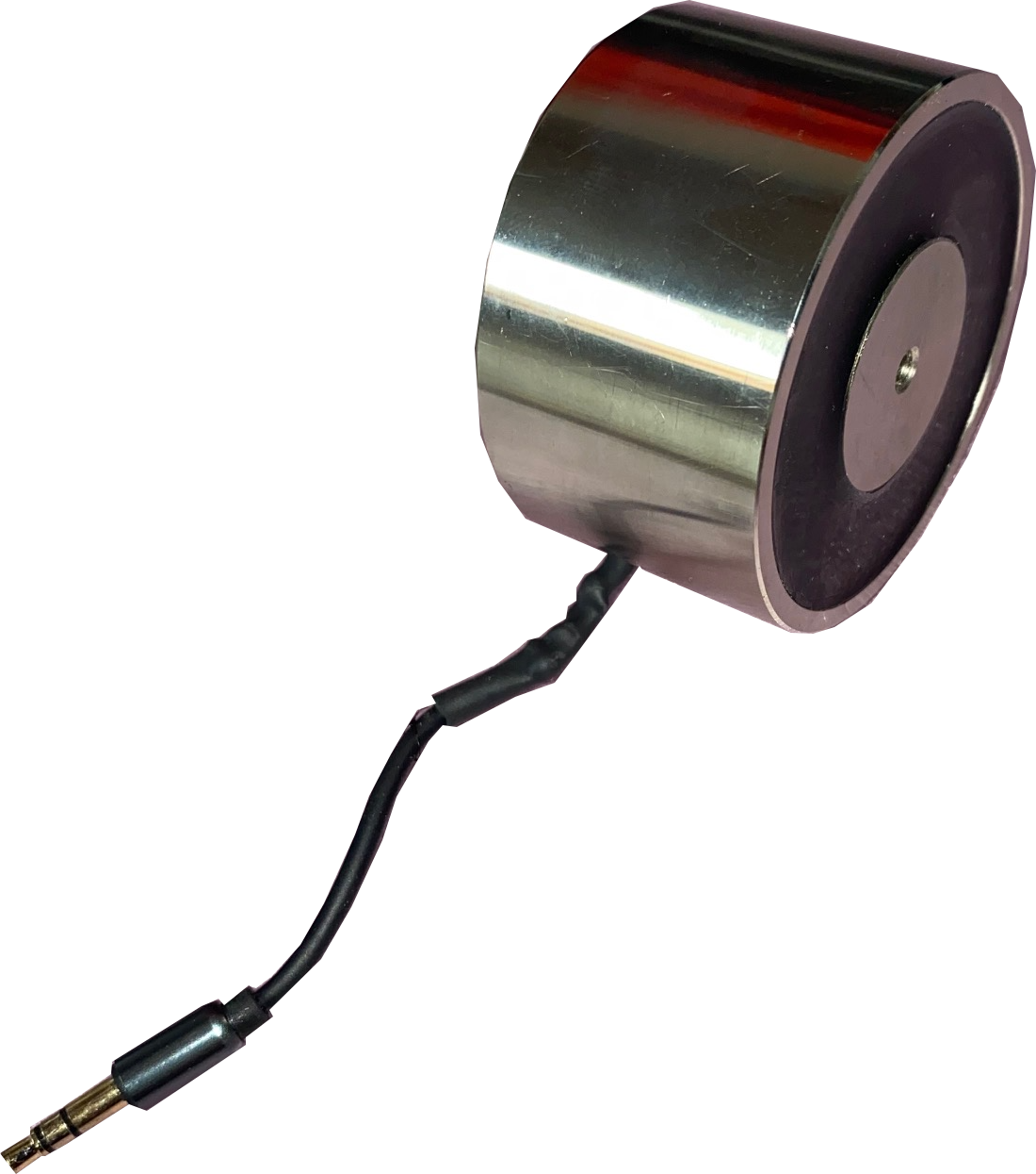
Magnetic attach plate
It is sometimes desirable to fix an antenna directly to a bare metal surface of a barrier. For example, when only one operator is available to pinpoint corresponding points on opposite sides of a barrier, that operator can, using an extension cord and magnetic attach plate, directly fix an antenna from a transmitter up to 18” away onto the bare metal surface of the barrier. Then, after turning the transmitter on, the operator can move to the opposite side of the barrier and use a receiver (or receive function on a transceiver) to pinpoint the location of the transmitter on the opposite side of the barrier.
Another application for the magnetic attach plate occurs when communicating through the barrier using the dedicated transmitter (as opposed to the transmitter in the transceiver). Because high power output levels of the dedicated transmitter can sometimes distort GO/STOP coded signals, placing the magnetic attach plate between the transmit antenna and the bare metal of the barrier is recommenced because this magnetic attach plate removes the signal distortions at high transmit power.
Below, a standard antenna, with an extension cord connected to a dedicated transmitter, is shown fixed to a metal wall with magnetic attach plate (shown without antenna on right).
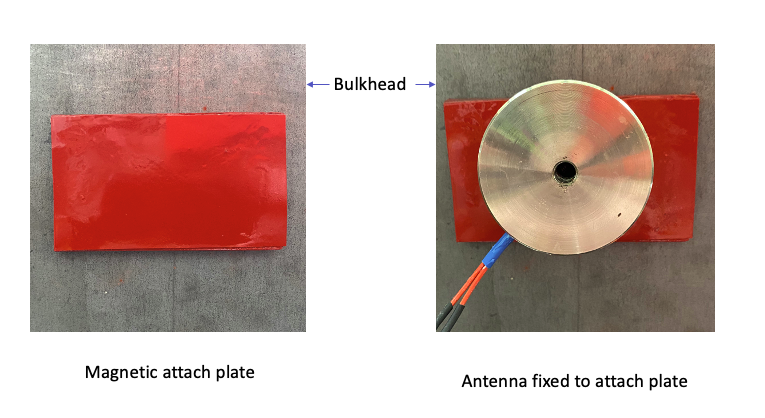
Magnetic attach plate
Remote units
The remote units have an optical receiver, indicator LED’s and speaker, and are designed to be carried or worn by operators who cannot easily see GO/STOP/URGENT messages displayed on a receiver’s screen.
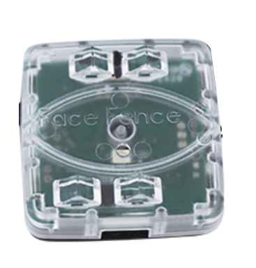
Front of remote signaling unit
Upon receiving a GO or STOP message via relayed from the Receiver unit to the the remote’s optical receiver, the remote flashes a GREEN GO or RED STOP
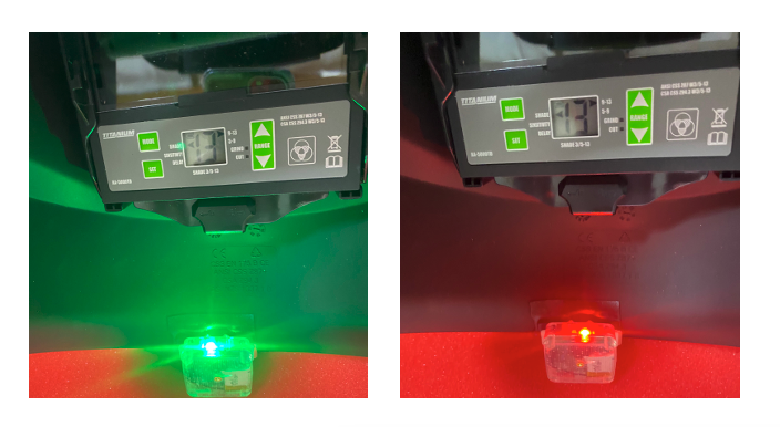
Below are shown GO (GREEN) and STOP (RED) indicators relayed through light pipes to back facing remotes
GREEN (GO) and RED (STOP) indications in remote unit magnetically attached in helmet
Control and charging of remote
The remotes are shown above facing backwards because typically, they will be mounted on a helmet, with the optical receiver facing forward in order to “see” around the bottom of the helmet. Below, a front view of the helmet shows a front-facing remote at the bottom of the helmet.
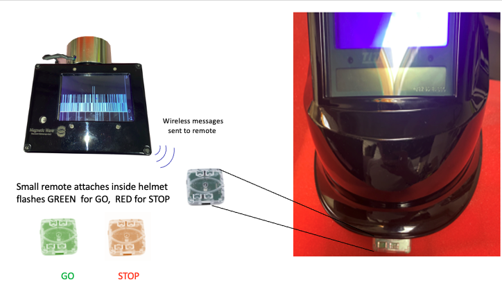
Remote attached inside welder’s helmet
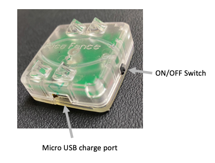
Charging the remote
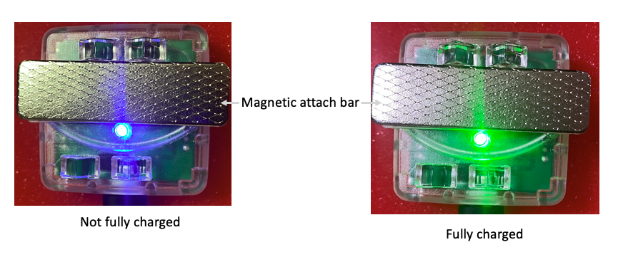
The remote units are charged via a micro USB port in their base. As shown below, when a USB power source is plugged in to the remotes, a Blue LED will light up if the remote’s battery is not fully charged.
When a full charge is achieved, a green light will replace the blue light.
NOTE: The green charge indicator is a separate LED from the GREEN “GO” LED at the top of the device.
Precisely locating a transmitter position through a metal wall
In most cases, except where very thick or unusual alloys in the wall are involved, when then is extreme electromagnetic interference or when there are many obstructions mounted on a wall where it is desired to pinpoint a specific position, precisely locating a transmitter’s position (specifically, the center of the transmitter antenna on the opposite side of the barrier) is straightforward using a multi-step process.
The steps for location finding
1) Using standard techniques, (measuring off of drawings, and known common fiducial points such as conduit throughways) determine the most likely point on one wall corresponding to a desired point on the opposite side of the wall. In all that follows, we will refer to the side of the wall with a known point “the known side” and the side of the opposite wall, where it is desired to find an exact corresponding point, the “unknown” side. WARNING: SUCH STANDARD TECHNIQUES MUST BE THE PRIMARY MEANS OF LOCATING POSITION. MAGNETIC WAVE MUST ONLY AUGMENT, NEVER REPLACE DIRECT MEASUREMENT METHODS
2) When the most likely position on the “unknown side” has been marked, one operator will place a transmitter antenna center on the correct point on the “known side,” then turn on the transmitter, selecting a power level appropriate for the thickness of metal, type of metal and amount of intervening insulation or other obstacles. The transmitter may be fixed in place with a permanent magnet, or held in place with a tripod mounted to the floor of the transmitter.
3) After the transmitter has been turned on, (and this act has been communicated via banging on the wall, or some other means) the operator on the “unknown side” will turn on the receiver, and place the center of the receive antenna over the marked spot.
4) Then, the “unknown side operator “ with the receiver will make sure that they have acquired a transmitter signal.
The figure on the left below is what the receiver screen looks like when there is only “noise”, and no real signal. The random spikes are simply magnified random noise. They appear large because of the autoscale feature of the system, where the displayed range is automatically adjusted according to the level of signal strength. Autoscaling makes sure that the full range of a signal can be seen, without “clipping off” of very low or very high signals. Thus, the vertical size of a signal on the display, all by itself, does not convey absolute signal strength. Rather the vertical extent of a signal, with reference to the scale on the right is what conveys absolute signal strength.
The figure on the far left below, represents the case where the initial estimate of the correct position on the “unknown side” is so far in error that there is no discernible signal at all. The middle figure shows how the signal appears in a weak form, when first acquired. This middle scan represents what an operator would see when moving from a “noise only” region into a “weak signal region” signifying that the receiver has moved closer to the true transmitter location.
On the far right a scan is shown in which the user progressively moved closer to to true position of the transmitter. In this example, the operator made two discrete moves, starting in a weak signal area and moving to progressively stronger regions.
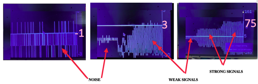
Noise (far left), weak signal (right side of middle) and song signals (far right)
In the middle figure, the difference between “noise” and weak signal can be clearly seen in two respects. First, the signal is larger and second, the signal is much more regular and less random.
5) Once a weak signal has been acquired, the operator should make a horizontal scan to find the point of greatest signal strength along that horizontal path. This point is determined by passing the receiver slowly across the point of estimated stringiest signal strength and the signal level number on the right, noting the point at which movement in either left or right direction decreases signal amplitude on the scan.
Motion should be no greater than 2”/sec, in order to avoid motion artifacts that mask the desired signal (more about this later)
6) At the point of greatest signal strength along the horizontal path, the operator should then move the receiver vertically, again until the strongest signal strength is achieved. As before, once the operator believe the strongest signal has been found they should slowly move the receiver onto and off of this point, ensuring that numeric values, shown on the far right, decrease away from the indicated point.
7) Operators should mark the point of greatest signal strength, then repeat the process several times to insure accurate location estimation. The figure below depicts the left/right up down scan pattern just described, where the operator started to the left and down of the correct point, started with and up/down scan, then, upon locating the peak signal strength inn up/down pattern, moved left and right until finding the peak on a horizontal pattern.
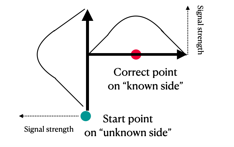
Scan pattern for pinpointing correct position
8) The importance of controlling speed of sensor motion across wall surface. When the receiver antenna moves across a ferrous metal plate, that movement, all by itself, will generate a slow, but potentially strong signal that can, if the motion is fast enough and signal weak enough, swamp out the signal and make location detection difficult, The figure below presents an example of a motion artifact, where the artifact occurred after the receiver antenna moved quickly away from an area where the signal was present to where no signal was present, creating an artifact.
In this example, with a very weak or absent signal, the motion artifact is not easily confused with a legitimate signal. However, too rapid of scan motion of the receiver when there is a signal present, can create confusion about whether a strong signal is or is not present.
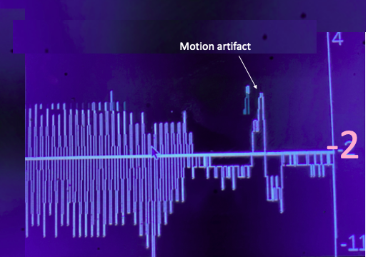
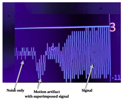
Motion artifact with superimposed real signal
In this second example, an operator moves the receiver antenna quickly from an a position with no real signal (noise only) to one with a weak signal. Because of the motion artifact, the amplitude (negative excursion) of the signal appears to be larger than it really is, as is evident from the gradual increase in signal strength as the receiver moves closer to the transmitter position. The second figure shows color spectrum bars at the top and left of the display, with a black vertical bar in each color bar indicating the instantaneous speed of receiver motion. As long as the vertical black bar stays in the green zone, or below (blue-green and blue), large motion artifacts will not interfere significantly with interpretation of the signal. But motion that places the vertical black bar in the yellow, orange or red, will produce a disruptive motion artifact that will make accurate judgments difficult.
Therefore, operators should pay close attention both to the speedometers in both axes, and to the possible presence of motion artifacts produced by rapid motion.
9) Communicating GO/STOP /URGENT messages. Before communication can occur, precise alignment of transmitter and receiver must take place, as described above, in order to achieve the best achievable signal strength. The point of maximal signal strength is called “The Alignment Point.” Often, during construction, the Alignment Point for communication will be different from the original Alignment Point marked for construction operations such as grinding or cutting, because the receiver would obscure work to be performed and the work itself could damage the receiver.
Thus, after the initial Alignment Point for performing work has been identified, a repeat Alignment Process must be performed, away from the original Alignment Point for work, the establish an Alignment Point for communications. When the work to be performed is likely to throw off sparks, slag or other heated debris, or when high voltage arc’s are created (as in arc welders, or plasma cutters), the Alignment Point for communications must be at least three feet away from the Alignment Point for work, to minimize electrical noise in the receiver from the high voltage arcs, which could interfere with the communication signal.
This need for at least three feet separation of the Alignment Points for work and communication, respectively, is the reason a remote communication relay is provided.
After operators on the “Known side” and “Unknown side” establish the Alignment Point for communication at least three feet away from the Alignment Point for work, the must test the communication of GO/STOP/URGENT messages, including successful relay of signals from the receiver to the remote device at least 3 feet away, before using the communication feature during construction operations. This test should include communication during test operation of high voltage sources such as arcs and plasmas.
If communication is not successful, either a new Alignment Point for communications must be selected and tested, as just described, or the communication feature must not be used.
To protect the receiver display rom sparks, slags or other harmful debris, it is recommended that a disposable transparent shield, of the kind used with welders helmet faceplates, is placed over the display to protect it.
After a successful test of communication, the operator on the “known side” of the metal wall will observe the effect that work on the opposite “unknown side” of the wall is having on the “known side”, and press the GO button on the transmitter when work may proceed, and STOP button, when work should cease.
WARNING: THE COMMUNICATION FEATURE OF MAGNETIC WAVE MUST NEVER REPLACE TRADITIONAL METHODS OF COMMUNICATION, SUCH AS BANGING ON THE METAL BARRIER WITH SIMPLE CODED MESSAGES (E.G. ONE BANG FOR GO AND TWO BANGS FOR STOP). RATHER, MAGNETIC WAVE SHOULD ALWAYS BE USED TO AUGMENT, NOT REPLACE SUCH TRADITIONAL METHODS.
Set-up prior to operation
1) Remove all units, together with antennas, charging cables and charging units from their packing materials.
2) Using the provided charging cables and chargers, charge all batteries in receivers, transmitters, transceivers and remotes as described earlier
3) Attach antennas to transmitter (or transceiver) and receiver units using the threaded studs on the front of the units, then plug in the male 3.5 mm phono jack connectors from the antennas into the female phono jack on the front of the units. Alternatively, plug the male connector from the antennas into the female connector of a provided extension cord, then plug the male connector of the extension cord into the female connector on the front of the unit
4) When charging is completed in all units, place the transmitter and receiver units, with attached antennas, facing each other about three inches apart, then turn on the transmitter (or transceiver), receiver, transmitter, receiver and remote.
5) Read the terms and conditions on the receiver (or transceiver’s) start up screen and either accept or decline the conditions.
6) If you accept the terms and conditions, the signal strength trace will scroll from right to left across your screen, with numeric signal strength indicator on the right, with a horizontal instantaneous signal strength bar and color bars for controlling speed.
7) You should see a strong signal waveform on the receiver unit (or transceiver acting in Receive Mode). Below, the beginning of a signal trace abut halfway through the scan can be see, indicating the transmitter was turned on at that point
8) Placing the remote device on the receiver as shown, alternatively press GO and STOP on the transmitter, to make sure that GO and STOP messages are relayed on the remote as GREEN and RED Lights respectively and that different GO and STOP tones play as appropriate.
Startup and test arrangement
9) If you have never previously used Magnetic Wave, you can get accustomed to its function by moving the receiver unit left right and up down with respect to the fixed transmitter to experience increases and decreases in signal strength with your movements. Below, slow movement to the left away from perfect alignment is shown.
Slight left offset shows signal strength-to-alignment relationship
10) Finally, by moving left/right and up/down at different speeds, while watching the left/right, up/down speedometers, you can learn what speed of motion will keep you in the GREEN zone or below, so as to avoid artifacts.
Safety warnings
1) Never use the Magnetic Wave system as the sole or primary means of locating positions or communication. The Magnetic Wave system is not guaranteed to either locate or communicate reliably under arbitrary conditions of metal wall thickness, metal barrier alloy make-up, presence of electromagnetic and optical interference, operator behavior to presence of obstacles and insulation.
2) Do not charge batteries of receivers, transceivers, transmitters or remotes unattended or overnight
3) When using devices near flying debris, especially hot debris such as slag, cover the units with transparent shield material similar to that that used on faceplate of welder’s helmets
4) Do not use the dedicated transmitter or the transmitter in a transceiver within three feet of any person wearing a pacemaker
5) Keep Magnetic Wave units dry at all times
6) Use and store Magnetic Wave systems in environments ranging from 0-35 degrees Celsius.
7) Keep operating Magnetic Wave transmit antennas at least three feet away from devices (such as magnetic stripe or magnetic disc drives) at all times.
8) Do not under any circumstances attempt to open the chassis case of transmitters, transceivers, receivers or remotes. Doing so could pose a shock hazard candor damage sensitive equipment.
9) Do not, under any circumstances, attempt to communicate directly with Magnetic wave embedded processors, for example, using the USB A maintenance/update ports.
10) Do not operate the Magnetic Wave system without completing Magnetic Wave Certified on-line training available at www.magneticwave.com/training. Operating the system without training will lead to unreliable locating and communicating.
11) Only operate the units in accordance with Magnetic Wave certified training and Operator’s manual. Use of the Magnetic Wave system outside the required procedures, described in training materials and the Operators Manual, will lead to unreliable communication and locating.
Troubleshooting guide
- Unit won’t turn on
Check battery charge
- Received signal not detectable
Insure transmit/receive antennas firmly in female connector
- Motion of receiver creates artifact
Slow receiver motion to GREEN or below
- Noise interferes with signal
Move antenna/receiver away from noise source
- GO/STOP messages don’t work
Insure that signal strength at least 10, low interference
- GO/STOP messages don’t reach
remote
Move remote to place where GO/STOP are received.
Move receiver closer to remote, if possible
Insure remote not exposed to direct sunlight
- Transmitter battery recharge
problems
Make sure set to LiPo and that recharge lights blinks.
System specification
SCOPE
The specifications (below) for system performance (e.g. location accuracy, allowed plate thickness) depend upon which combinations of components are used.
The highest level of accuracy and plate thickness is achieved using a transmitter set on the highest output power setting with a receiver on the opposite side of a barrier equipped with an ultra-sensitive antenna, whereas lesser performance (accuracy and plate thickness) is achieved with other combinations of antennas and transmit output power.
Thus, specifications here are tied to specific combinations of components.
One last point: all specifications are described for typical alloys of steel plates, types of insulation and environmental conditions such as ambient electromagnetic noise (both radio frequency and optical). Performance numbers described here will not be achieved with arbitrary alloys, mill scale present on metal plates, types of insulation and electromagnetic interference. Although the reference manual describes ways to work around interference, Magnetic Wave makes no guarantee of system performance for all types and thicknesses of materials and working environments. Also, all specifications assume that operators are fully trained on using the system and use it according to instructions in training material and the operator’s manual.
Location accuracy
The accuracy of location-finding of the center of the transmit antenna located on one side, measured on the opposite side of a barrier depends primarily upon four factors
1) Plate thickness
2) Insulation thickness
3) Type of receive antenna
4) Training and skill of the operator
Other factors, such as strong electromagnetic interference and mechanical vibration of the plate due to operation of nearby machinery can degrade location accuracy as well, but these have not yet been fully characterized and have not proven to be problematic under conditions tested thus far. This specification will be updated as more data on these other factors becomes available.
Accuracy degrades with increasing plate thickness, presence of insulation, and sometimes, use of the long probe antenna.
The tables below, which show accuracies for different plate thicknesses and antenna types present cases where no insulation is present and where 2” of insulation is present. N/A indicates use of a particular antenna for a particular thickness is not recommended.
Table 1
| .25” | .375” | .5” | 1” | 2” |
Standard | .5” | .5” | .5” | N/A | N/A |
Long Probe | .5” | .5” | .5” | N/A | N/A |
Ultra-sensitive | N/A | N/A | .5” | .75” | .75” |
Location accuracy with different antennas and plate thicknesses: No insulation
Table 2
| .25” | .375” | .5” | 1” | 2” |
Standard | 1” | 1” | 1.5” | N/A | N/A |
Long Probe | 1” | 1.5” | 1.5” | N/A | N/A |
Ultra-sensitive | N/A | N/A | 1’ | 1” | 1” |
Location accuracy with different antennas and plate thicknesses: 2” insulation
For example, with plate .375” thick or less, an ultra-sensitive antenna is not required, whereas with plate of greater thickness than .5”, only an ultrasensitive antenna will yield acceptable results.
The data in the tables above demonstrates that, when very high accuracy is desired, insulation should be removed to allow the receive antenna to abut directly on a bare metal surface.
Thus, an appropriate area of insulation to be removed (for example a 3” X 3” patch) can be identified and marked based upon a first pass of the receiver with insulation in place, then, after the insulation patch is removed, a second pass of the receiver antenna on bare metal under the recently removed insulation can locate the desired point at greater accuracy, as indicated by the tables
With practice, operators can improve their ability to pinpoint correct locations by learning a few tricks, such as “splitting the difference” on a “signal plateau”
The figure below, which is a reconstruction of signal strength vs position relative to the true location of a transmit antenna, as measured by an ultrasensitive antenna on the opposite side of the plate from the transmitter, shows such a “signal plateau” for a 2” plate with 2” insulation.
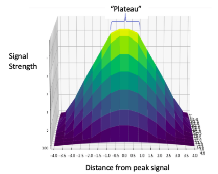
The figure shows that, as the receiver antenna is moved away from the point of peak signal strengths (yellow), signal strength falls gradually within an inch of the peak, then falls rapidly at distances greater than 1”
Thus, there is a roughly 2” plateau (+/- 1” from the peak signal position), where movement of the receiver antenna will produce relatively small changes in signal strength, making precise locating more difficult.
However, skilled operators can identify the “edges” of this plateau, then identify the peak position as midway between those two edges, because signal strength falls off uniformly in all directions away from a signal peak.
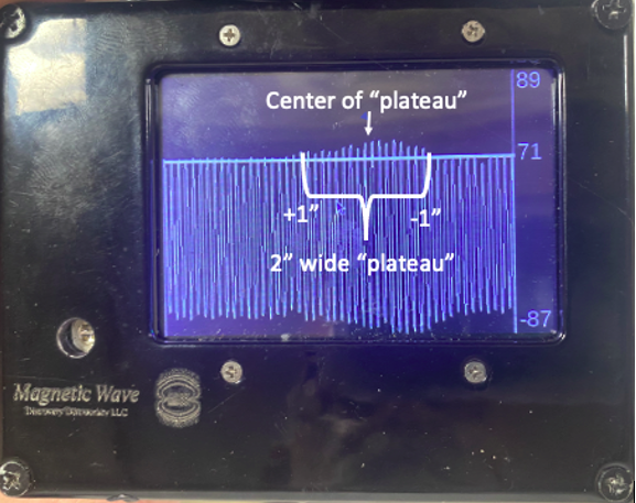
The figure below is a screen shot after an operator slowly moved the receiver antenna about 2” across the peak signal location. The shallow hump in the signal amplitude represents slight, but persistent changes in signal amplitude, corresponding to the “plateau” region of the previous figure. By taking careful note of the receiver antenna position when the midpoint of the hump occurs, an operator can identify the correct spot to within +/- .5” even though the “plateau” itself may span as much as 2”, as shown below.
Communication between transmitter & receiver through plate/insulation
Messages
Screen GO/STOP/URGENT
IR transmitted to remote GO/STOP/URGENT
Future growth feature* Arbitrary Text
Plate thickness Up to 6” steel plate
*Through touchscreen keyboard, USB keyboard
Or USB microphone-to-speech-to-text
Characteristics with standard antennas
Battery life
Receiver 3 hours (continuous)
Transmitter 3 hours (continuous): low power
1.5 hours (continuous): high power
Battery recharge
Receiver 5V Micro USB, 1- hour recharge
Transmitter 11.1V, DIN, 1-hour recharge
Size (Both transmitter and receiver chassis) 4.75” W X 3.75” H X 2.25” D
Size (Standard antenna) 2.25” diameter X 1.375” depth
Weight
Chassis 1.4 lbs.
Antenna 1.1 lbs.
Chassis + antenna 2.5 lbs.
Characteristics with long probe receive antenna
Weight
Chassis 1.4 lbs.
Antenna 1.3 lbs.
Chassis + antenna (narrow probe) 2.7 lbs.
Characteristics of ultra-sensitive antenna (using extension cord to chassis)
Size 2” diameter X 7” long
Weight 3.4 lbs.
Remote signaling device
Range from receiver/transceiver 3 feet
Alerts Lights/Tones
RED+BUZZ=STOP
GREEN+RING=GO
RED FLASH+BUZZ=URGENT
Attachment Magnetic badge type
Battery life 8 hours continuous
Battery charge Micro USB, 5V
Battery charge time 20 minutes
Size 1.5” X 1.5” X .75”
Weight 11 Grams